Exchange the CEC enclosure disk drive backplane
Before you begin
CAUTION:
This assembly contains mechanical moving parts. Use care when
you service this assembly. (C025)
 Use approved ESD procedures to prevent damage.
Attention:
- This procedure is not a stand-alone procedure. Customer disruption and damage to the hardware might occur when microcode and power boundaries are not in the proper conditions for this service action.
- If a serviceable event FRU repair directed you to this procedure, the microcode and power boundaries are already set.
- If a serviceable event FRU repair did not direct you to this procedure, see MAP1230 Replace a FRU without using a serviceable event.
Notes:
- All the cables and FRUs to be removed must be uniquely identified so they can be reinstalled correctly.
- If an installed earthquake resistance kit prevents you from accessing this FRU, refer to MAP1600.
Preparing the CEC enclosure to remove and replace the disk drive backplane
Procedure
-
Use the front and rear blue identify LEDs to determine the CEC enclosure to be repaired. Both
blue LEDs should be lit.
- CEC control panel blue identify LED
 as shown
in Figure 1.
as shown
in Figure 1. - CEC enclosure rear blue identify LED
 as shown
in Figure 2.
as shown
in Figure 2.
Note: If both the front and rear CEC enclosure identify LEDs are not lit, use the location code listed in the serviceable event FRU list. See MAP1245 Finding FRUs by using location codes.Figure 1. Control panel LEDs 
Figure 2. CEC enclosure rear LEDs 
- CEC control panel blue identify LED
-
Verify that the CEC enclosure is in the power-off state. See Figure 3
Figure 3. Location of the power supplies and LEDs (Model 982) 
-
Disconnect the power cords from the
CEC with the DC (output) LEDs flashing. See Figure 4.
Notes:
- Ensure the power cords are correctly labeled.
- The power supply LEDs might continue to flash for up to 20 seconds while internal power is discharged.
- The power cord is fastened to the system using the hook-and-loop fastener
 . Unstrap
the fastener to allow the enclosure to be placed in the service position.
. Unstrap
the fastener to allow the enclosure to be placed in the service position.
Figure 4. Removing the power cords (Models 982, 988) 
-
Observe the CEC enclosure control panel green power button LED . See
Figure 5.
- If it is off, go to the next step.
- If it is flashing, the CEC enclosure is still in the power-off state. DO NOT CONTINUE. Ensure that you have unplugged the power cables.
Figure 5. Control panel LEDs -
Remove the front cover.
CAUTION:A hot surface nearby.

- Ensure that you have the electrostatic discharge (ESD) wrist strap attached. If not, attach it now.
-
Place your fingers on the indentations and pull the latches
located on both sides of the cover.
-
Pull the cover away from the system.
Figure 6. Removing the front cover 
Removing the CEC enclosure disk drive backplane
About this task
To remove the CEC enclosure disk drive backplane, complete the following steps:
Attention: When the disk drive backplane is separated from the RAID assembly, electronic
components on the disk drive backplane are exposed to possible damage due to handling. Be careful
when you handle the disk drive backplane to prevent damage to exposed electronic components on the
disk drive backplane.
Procedure
-
Loosen, but do not remove the recessed shipping screws in the
RAID assembly by using a 4 mm Allen wrench, as shown in Figure 7.
Figure 7. Loosening the shipping screws 
-
Remove the control panel.
- Press the terracotta tab and then slide the control panel straight out of the slot. See Figure 8.
- Place the control panel on the ESD mat.
Figure 8. Removing a control panel 
-
Remove the DVD drive filler. See Figure 9.
Note: DVD is shown for location.
Figure 9. Removing the DVD drive 
-
Label and remove the disk drives and fillers.
-
Unlock the drive handle by pressing the handle latch
and pulling it toward you, as shown in Figure 10. If the handle is not all the way out, the disk
drive cannot slide out of the system.
- Support the bottom of the drive as you slide it out of the system. Do not hold the drive by the handle.
- Place the drive on the ESD mat.
- Repeat step 5 for the remaining disk drives and fillers.
Figure 10. Removing the disk drive 
-
Unlock the drive handle
-
Label and remove the solid-state drives (if present) and fillers.
-
Unlock the drive handle by pushing the handle latch
in the direction that is shown and pulling the drive handle
out toward you, as shown in Figure 11. If the handle is not all the way out, the
solid-state drive cannot slide out of the system.
- Support the bottom of the drive as you slide it out of the system. Do not hold the drive by the handle.
-
Lock the drive handle by rotating it inwards toward the
system.
- Place the solid-state drive on the ESD mat.
- Repeat step 6 for the remaining solid-state drives and fillers.
Figure 11. Removing the solid-state drive 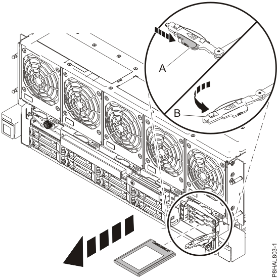
-
Unlock the drive handle
-
Turn the thumbscrews in the direction shown. Pull out the latches and remove the RAID assembly
from the system, as shown in Figure 12.
Figure 12. Removing the RAID assembly from the system 
-
Turn the RAID assembly upside down and place the assembly on a flat surface, as shown in Figure 13.
Figure 13. Turning the RAID assembly upside down 
-
Press down on the RAID assembly cover latches , then slide the
cover in the direction that is shown and lift to remove it, as shown
in Figure 14.
Figure 14. Removing the RAID assembly cover 
-
Remove four screws from each side of the RAID assembly by using a T10 Torx screwdriver. See
Figure 15.
Figure 15. Removing screws from the RAID assembly 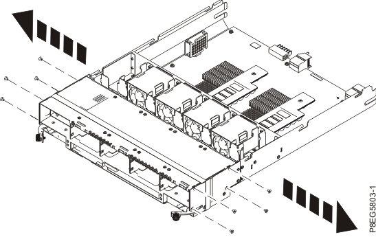
-
Grasp the disk drive backplane with both hands and pull it
toward you until pins on the bottom side of the disk drive backplane,
clear the RAID assembly slot. Then, lift the disk drive backplane to remove it, as shown in Figure 16.
Figure 16. Removing the disk drive backplane 
Replacing the CEC enclosure disk drive backplane
About this task
To replace the CEC enclosure disk drive backplane, complete the following steps:
Attention: When the disk drive backplane is separated from the RAID assembly, electronic
components on the disk drive backplane are exposed to possible damage due to handling. Be careful
when you handle the disk drive backplane to prevent damage to exposed electronic components on the
disk drive backplane.
Procedure
-
Slide the disk drive backplane into position on the RAID
assembly. Ensure the pins on the bottom side of the disk drive
backplane are inserted into the slots on the RAID assembly. See Figure 17.
Figure 17. Replacing the disk drive backplane 
-
Replace four screws on each side of the RAID assembly by using a T10 Torx screwdriver. See
Figure 18.
Figure 18. Replacing the screws 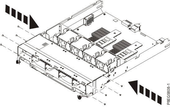
-
Slide the RAID assembly cover in the direction that is shown
until the latches lock in position, as shown in Figure 19.
Figure 19. Replacing the RAID assembly cover 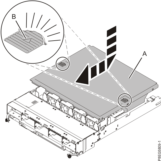
-
Turn the RAID assembly over, as shown in Figure 20.
Figure 20. Turning the RAID assembly over 
-
Slide the RAID assembly into the system. Push latches in and tighten thumbscrews, as shown in
Figure 21.
Figure 21. Replacing the RAID assembly 
-
Replace the disk drives and fillers into their original positions.
-
Unlock the drive bay handle by pressing it and pulling it out
toward you. If the handle is not all the way out, the drive does not slide into the system.
-
Slide the drive all the way into the system, and push the drive bay handle
in until it locks, as shown in Figure 22.
Important: Ensure that the drive is fully seated and is all the way into the system.
Figure 22. Replacing a disk drive 
-
Unlock the drive bay handle
-
Replace the solid-state drives (SSD) (if removed) and fillers into their original
positions.
-
With the solid-state drive handle in the unlocked position, pull
the lever outward to gain access to the guide rails in the SSD slot. Support the bottom of the SSD
as you align it with the guide rails in the SSD slot.
Note: Do not hold the drive only by the handle. Support the drive by holding the drive by its sides.
-
Slide the SSD into the system until the drive stops, and then lock the SSD by rotating the
handle in the direction shown.
Important: When you install an SSD, ensure that the SSD is fully seated and is all the way into the system.
-
Lock the drive by rotating the handle in the direction that is
shown in Figure 23.
Figure 23. Replacing the solid-state drive 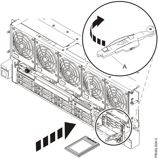
-
With the solid-state drive handle
-
Replace the DVD drive filler. See Figure 24.
Note: DVD is shown for location.
Figure 24. Replacing the DVD drive 
-
Replace the control panel.
- Align the control panel with the control panel slot.
- Slide the control panel into the slot, and press on the terracotta tab to lock it in place. See Figure 25.
Figure 25. Replacing the control panel 
Preparing the CEC enclosure for operation after removing and replacing the disk drive backplane
About this task
To prepare the system for operation, complete the following steps:
Procedure
-
Replace the front cover.
- Ensure that you have the electrostatic discharge (ESD) wrist strap attached. If not, attach it now.
-
Position the cover on the front of the system unit so that the
four pins on the system match the four holes at the rear of the
cover.
-
Press the tabs
 to snap the cover into position.
Figure 26. Installing the front cover 
-
Reconnect the power cords to the
CEC enclosure. See Figure 27.
-
Fasten the power cords to the enclosure using the hook-and-loop fasteners .
Figure 27. Connecting the power cords 
-
Verify that the CEC enclosure has power available. See Figure 28.
Figure 28. Location of the power supplies and LEDs (Model 982, 988) -
Wait up to 5 minutes for the CEC enclosure control panel power-button LED to flash.
See Figure 29.
Note: This ensures the CEC enclosure is in the power-off state.
Is the power-button LED flashing?
- Yes, go to the next step.
- No, ensure the CEC enclosure power supplies are fully seated. The possible failing FRUs are the CEC enclosure system backplane, I2C interface card and cables, and control panel. You can also call the next level of support.
Figure 29. Control panel LEDs